Changes considered for production tubes.
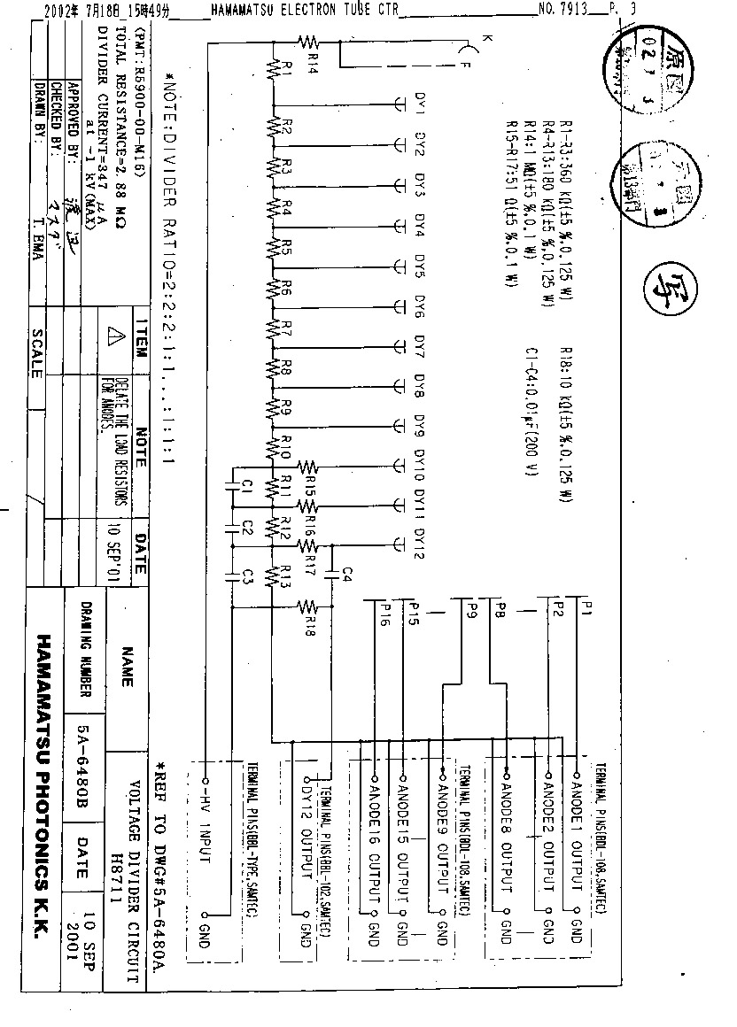
 Remove resistors between the final dynode stage and the anodes,
R18 - R33.
This is to be compatible with QIE/SMQIE.
Charge-up problem?
SMQIE has to determine the ground level and thus the anode level.
Cause a difference from the HV ground?
Add a 300-Ohm resistor between HV shield and anode shield?
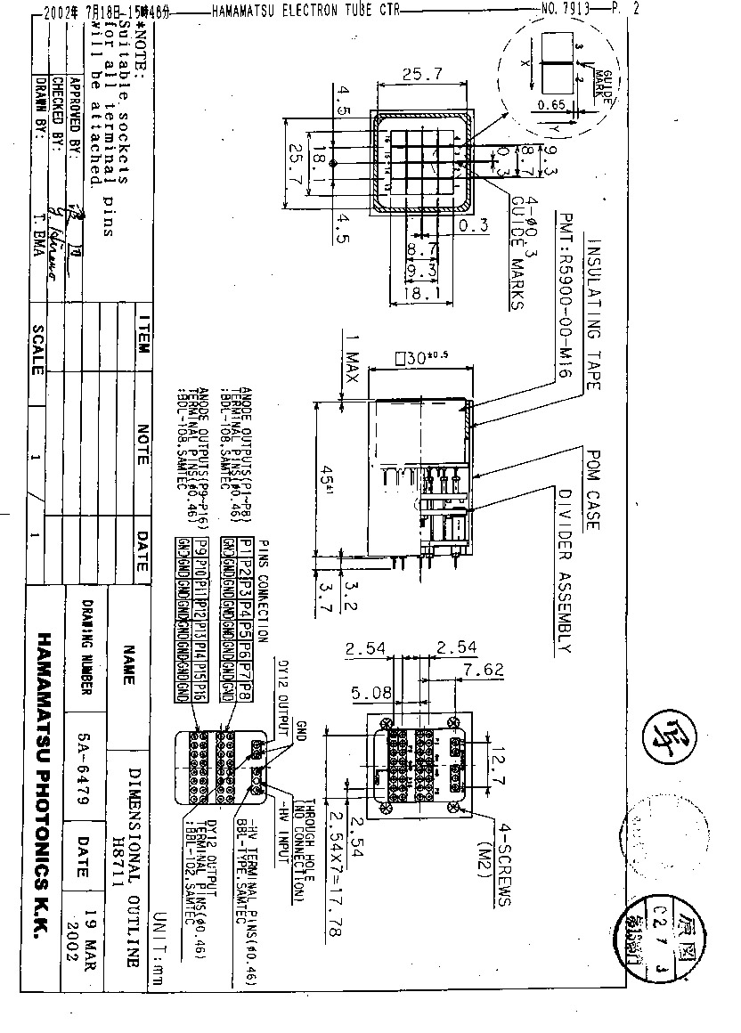
Anode pin output instead of cables.
Like one in
H7546 (64 ch), but with individual ground
pins.
Remove resistors between the final dynode stage and the anodes,
R18 - R33.
This is to be compatible with QIE/SMQIE.
Charge-up problem?
SMQIE has to determine the ground level and thus the anode level.
Cause a difference from the HV ground?
Add a 300-Ohm resistor between HV shield and anode shield?
Anode pin output instead of cables.
Like one in
H7546 (64 ch), but with individual ground
pins.
 H8711 drawings :
1 -
2 (HV is also a pin),
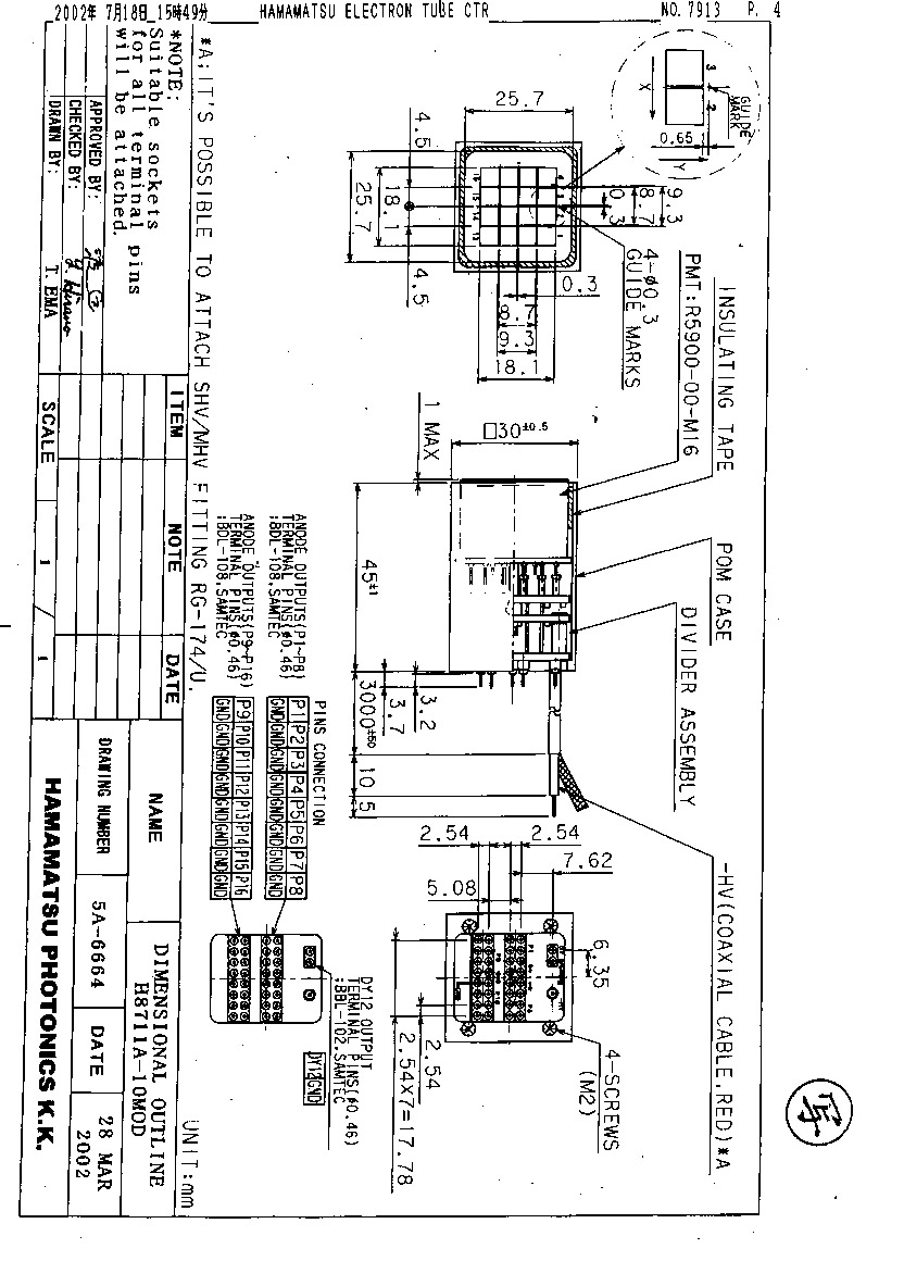
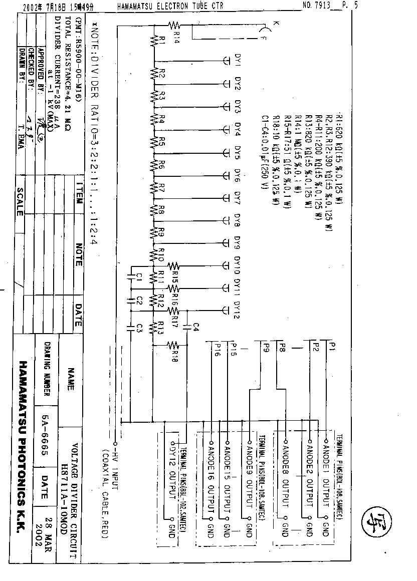
3 -
4 (HV coax cable)
H8711 drawings :
1 -
2 (HV is also a pin),
3 -
4 (HV coax cable)
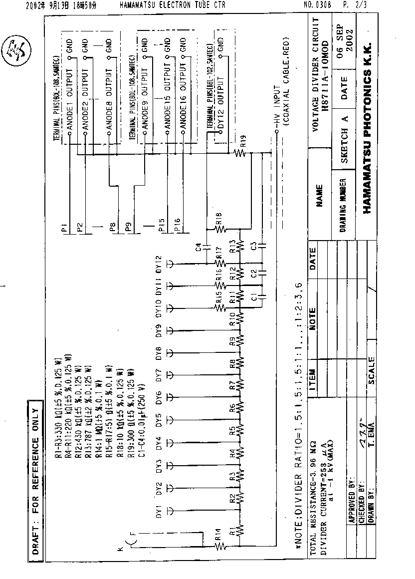
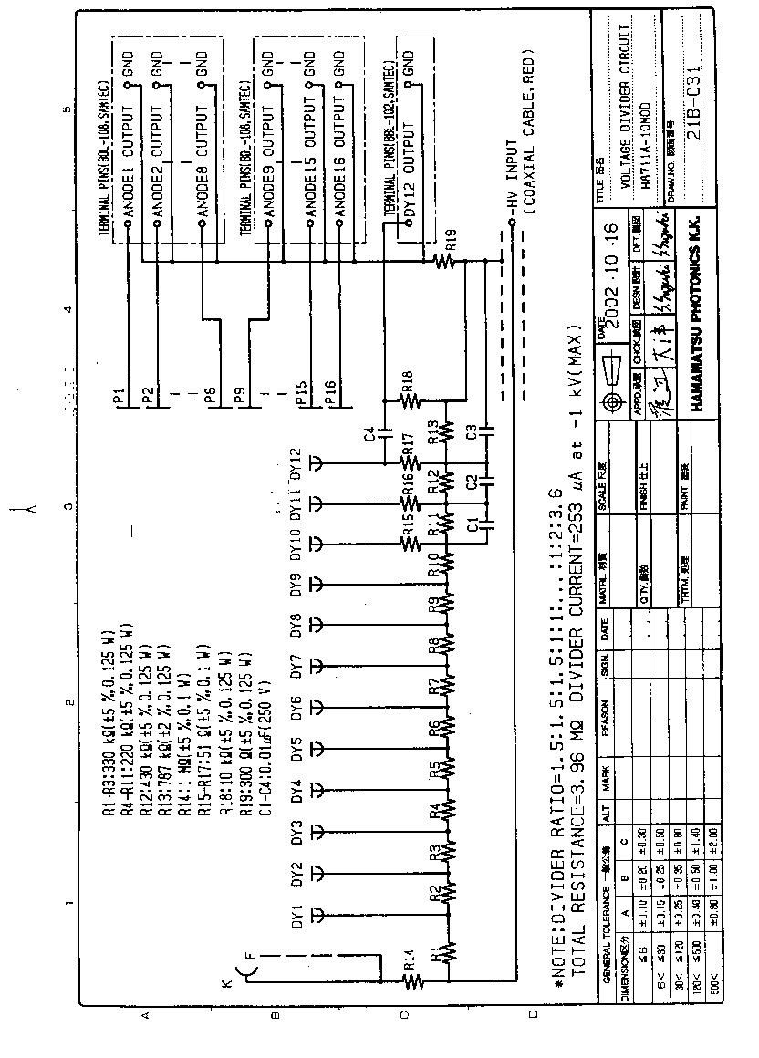
Use the tapered voltage divider for a factor of 10 better
pulse linearity (dynamic range).
The ratios will be 1.5 : 1.5 : 1.5 : 1 : 1 ... 1 : 2 : 3.6.
This should ease the space-charge effects at the last synode stages,
though the overall gain will be reduced by roughly a factor of 5 (at -800 V).
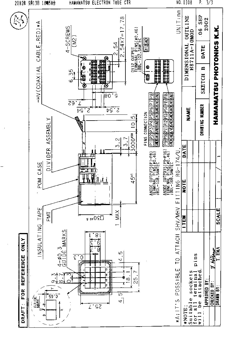
Design proposal : Sept 2002
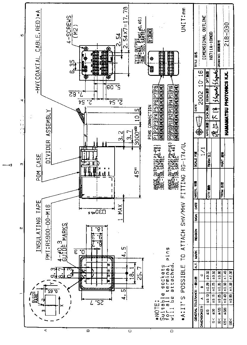
H8711A-10MOD drawings :
Electrical -
Mechanical
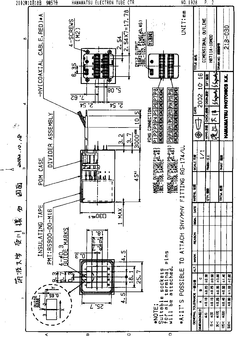
Oct 17, 2002. Order placed for ten H8711A-10MOD tubes.
To be shipped from Hamamatsu to Tsukuba on Dec 20, 2002.
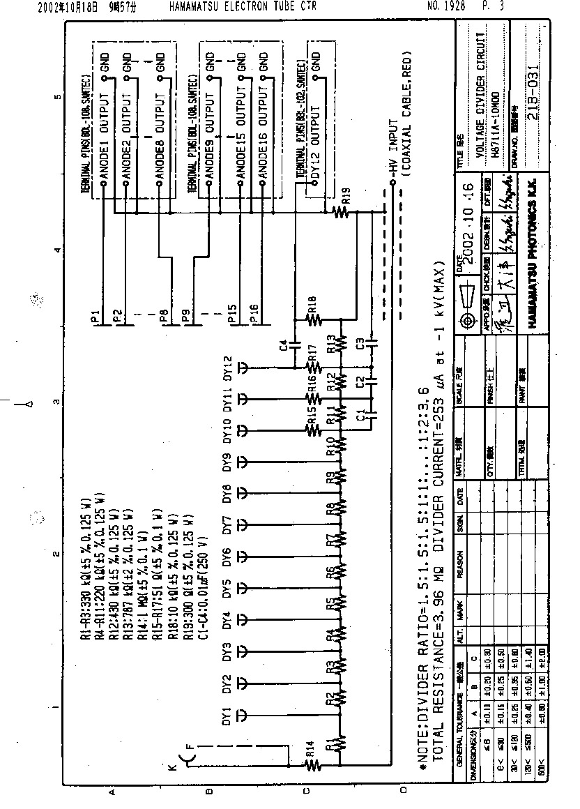
Final drawings:
Mechanical -
Electrical
Delivered on Dec 24, 2002.
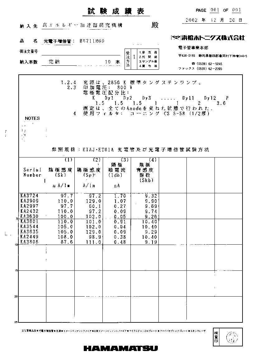
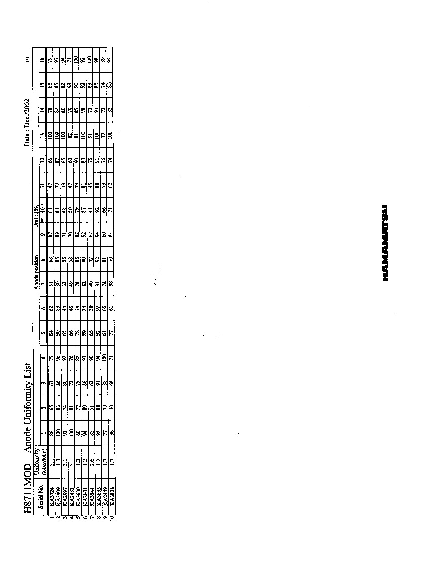
Tube data by Hamamatsu:
Data sheets -
Anode uniformity -
Mechanical drawing -
Electrical drawing
Pictures: (including the interface PC board
prototype)
Real size of the anode pixels
(Aug 30, 2002)
PMT box design as of
Nov 2002 (from Bob Miller, MSU)
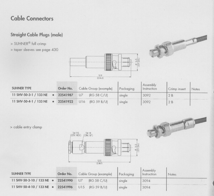
And a matching HV connector candidate
11 SHV-50-3-1 on the PMT side.
Nov 14, 2002 :
A further modification of the pins is being asked
so that we can attach TSW-type connectors
(e.g. TSW-108-07-?-D)
on the PMT.
This is under consideration by Hamamatsu.
Feb 14, 2003 :
H8711A-10MOD (21B-030A) drawings :
pdf file
(both mechanical and electrical, though no change to electrical)