Testbench system
 Design of the ISL and the sensor
An isometric view of the ISL barrels is here ( GIF view ).
The microstrip sensors are processed on 4" or 6" wafers.
The dimensions of 4" prototype sensors from Hamamatsu ( GIF view) is determined to utilize the maximum available area. The dimensions of 4" SEIKO sensors are similar (the outer dimensions are identical).
Six of such sensors are aligned to construct a ladder.
The strips run along the beamline for the n-side and at a small stereo angle of 1.207deg for the p-side. This angle is determined such that the stereo strips are aligned on a line when the neighboring sensors are positioned at a gap space of 100 microns ( GIF view ).
The phi-acceptance of ISL barrels is plotted here ( GIF view). The plot shows how the acceptance is degraded with increasing the number of stereo strips which are not read out. 12 strips at the corner are short and not readout, though they are biased so that the field at the corner is not distorted. Wirebonding three sensors, 36 strips at the corner are not read out per half ladder. The plot shows the phi acceptance is not degraded at all - we have enough overlapping between the sensors.
The specifications of 4" prototype sensors are summarized in this list ( PS file). The pad position is shown here( GIF view ). A constraint concerning the pad position is the wire length be shorter than 3 mm. A scheme of staggering the pads is avoided to simplify the wirebonding procedure.
Details of the structure of the 4" ISL sensor
The design of the sensor is based on the various studies carried out in designing Hamamatsu SVX-II sensors. The implant strip width is 22 microns to match the strip pitch of 112 microns. The Al electrode width is set to 16 microns so that the Al electrodes are recessed by 3 microns from the implant strips, thus suppressing the micro-discharge.
- p-side structure of 4" SEIKO prototype GIF view
- n-side structure of 4" SEIKO prototype GIF view
The drawings above are for the SEIKO prototype. The main differences between the two manufactures are the materials at the coupling capacitance and the passivation. The differences are shown here ( GIF view , EPS file ).
Performance of the 4" ISL prototypes
The QC items by each manufacturer are summarized in these tables, Hamamatsu
( GIF view: EPS file)
and SEIKO ( GIF view: EPS file). The characteristics plots include:
Number of dead coupling capacitors
- SEIKO judges dead coupling capacitance from the leak current (0.1 microA) when
100 V is applied across the DC and ADC pads. The capacitor can stand at
higher voltages but bad capacitors show leakage current at this voltage.
The number of dead capacitaors is histogrammed for the 9 prototype sensros.
- Hamamatsu judges dead coupling capacitance from transient current induced when
a pulse of 100 V is applied across the dedicated strip located at ends of implant strips and AC pads at the other ends. This way short capacitors (large currents), open Al electrode (small currents) and contacting Al electrodes (current larger scaling with the number of contacting strips) can be detected.
-
Poly-Si resistance of 9 SEIKO prototype sensors
The resistance was measured for test structures located outside the sensor. There are five structures per side uniformly distributed corresponding to the resistors at the middle, sides, and in between.
-
leakage current from individual channel
The leakage current induced at individual channel is measured by probing
the individual DC pad while bias voltage of 120 V (Hamamatsu) or
100 V (SEIKO) is applied.
Measurement is done only for the p-side, since the device can be biased
from the same side only on p-side. The sample Hamamatsu-18 has only one
leaky channel, and the sum of the all individual currents is equal to the
total leakage current measured at 120V, 0.3 microA. The two samples by SEIKO
show some clusters of leaky channels.
33 strips per side and bias lines are wirebonded on a test printed board . Main characteristics measured at University of Tsukuba are:
-
Total leakage current vs. bias voltage
The bias voltage is applied across the p and n bias rings and the current is measured with Keithley 485 picoammeter.
- I-V curve of the 3 Hamamatsu prototype sensors PS file .
- I-V curve of the 8 SEIKO prototype sensors PS file .
-
Bulk capacitance vs. bias voltage(frequency dependence)
The bulk capacitance is measured with HP4275A LCR meter with varying the frequency from 10 kHz to 10 MHz.
- Bulk Capacitance vs. bias voltage of Hamamatsu sensor PS file .
- Bulk Capacitance vs. bias voltage of SEIKO sensor PS file .
- Bulk Capacitance measured at 10 kHz. Hamamatsu and SEIKO sensors are compared PS file .
-
Interstrip capacitance vs. bias voltage (frequency dependence)
The interstrip capacitance is measured in two configurations: C1 is the capacitance between two neighboring Al strips while the others are floating, C2 is the capacitance between one Al strip and one neighboring strips on each side while the others are floating.
- C1 interstrip capacitance of SEIKO sensor (n-side)
- C2 interstrip capacitance of SEIKO sensor (n-side)
The strips in the above measurements are the one at the middle of the sensor.
Performance related to Co-gamma irradiation
Co irradiation was performed on January 26, 1998 for two sensors each for Hamamatsu and SEIKO.
Total leakage current during and after exposure
The sensors were exposed at a fixed rate of 35 krad/h for a total of 5 hrs.
The leakage current vs. bias voltage was measured before irradiaiton, after
1 krad, 7 krad, 35 krad, and 160 krad.
Total current as a function of time during Co exposure; average of two Hamamatsu sensors, two SEIKO sensors.
The total leak current at fixed bias voltages (Vb=120V for Hamamatsu,
75V for SEIKO) was traced after irradiation. The sensors were kept at 20 degC.
The bias voltage was off for the first 30 hr, then was kept on after except
the period when I-V characteristics were measured.
Total current as a function of time after Co exposure; average of two Hamamatsu sensors, two SEIKO sensors.
I-V curves at different doses
Changes in the interstrip capacitances
The interstrip capacitance C2 was measured 1 week after irradiation.
We notice an increase in the voltage where the interstrip capacitance is
minimized. Charge accumulation degrades the isolation between strips, thus
we require to apply larger voltage to do so.
Changes in the bulk capacitances
The bulk capacitance was measured 1 week after irradiation. The frequency
at 10 kHz.
Testbench system
Production Sensors
A-class sensors are delivered to FNAL while some B- and C-class sensors
(sensor with *) are probed at Tsukuba in order to monitor the production
batches. The sensor number is laser printed on p-side in a binary.
- H0001: I-V
- H0002: I-V
- H0003*: I-V,
I-strip
- H0004*: I-V,
I-strip
- H0005*: I-V,
I-strip
- H0001-H0023 I-V curves.
H0003-0005 are B class sensors, which are delivered to U Tsukuba.
- H0024-H0027 I-V curves,
shipped on Dec 24, 1998.
- H0028-H0055 I-V curves,
shipped on Jan 28, 1999 (A-class sensors).
- H0056-H0073 I-V curves,
shipped on Jan 28, 1999 (B-class sensors with p-side strip current probed).
- H0074-H0107 I-V curves, shipped on Feb 28, 1999 (A-class sensors).
- H0108-H0122 I-V curves, shipped on Feb 28, 1999 (B-class sensors with p-side strip current probed).
- H0123-H0162 I-V curves, shipped on March 25, 1999 (A-class sensors).
- H0163-H0194 I-V curves, shipped on March 25, 1999 (B-class sensors).
- H0205-H0232 I-V curves,
shipped on April 27, 1999 (A-class sensors).
- H0233-H0242 I-V curves,
shipped on April 27, 1999 (B-class sensors).
- H0243-H0250 I-V curves,
shipped on May 29, 1999 (A-class sensors).
- H0251-H0256 I-V curves,
shipped on May 29, 1999 (B-class sensors).
- H0270-H0288 I-V curves,
shipped on July 30, 1999 (A-class sensors).
- H0289-H0327 I-V curves,
shipped on August 31, 1999 (A-class sensors).
- H0328-H0345 I-V curves,
shipped on September 16, 1999 (A-class sensors, H341 missing).
- H0346-H0377 I-V curves,
shipped on September 16, 1999 (B-class sensors).
- H0381-H0400 I-V curves,
shipped on September 30, 1999 (A-class sensors).
- H0401-H0430 I-V curves,
shipped on September 30, 1999 (A-class sensors).
Co-60 irradiation of Class B sensors
Three sensors H0196-198 were irradiated with Co-60 gammas to 0.2 Mrad.
Individual strip currents were compared before and after the irradiation.
The post irradiation measurements were made 2-4 days after (The sensors
are still underway of annelaing). The average leakage current of good
strips increased from 1 nA to 50 nA. Leaky strips (>100 nA or so) remain
to be leaky but there is no radiation induced increase in the leakage current
nor the neighboring strips are affected.
Long-term stability
In total seven sensors are kept biased at 120V in a thermostat chamber where
the temperature is controlled at 20degC. The total leakage current of these
sensors are measured at 120 and 150V. The bias was raised to 150V for a period
of ca.1min for this measurement.
Th seven sensors are of grade A (199,200,201), of grade B (195,202) and of
grade C (203,204) in terms of the IV characteristics (they fail dead channel fraction, though). See the IV curves measured by HPK (at 25degC).
We note the leakage current of 203 at 120V droped substantially in a couple of
days. To see what happened to this and to other sensors, the IV
characteristics was measured 5 days after biasing .
Comments: sensors 195 and 199 have been probed at Tsukuba. No instabilities are
seen for these sensors, instabilities being expected if the sensors are damaged.
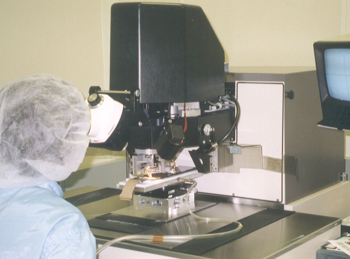
Ladder construction procedure
The sensors are assembled into half-ladders, each consisting of 3 sensors.
Two half ladders are glued together, making a full ladder. The assembling is
performed at Fermilab with using assembling jigs constructed by Karlsruhe group.
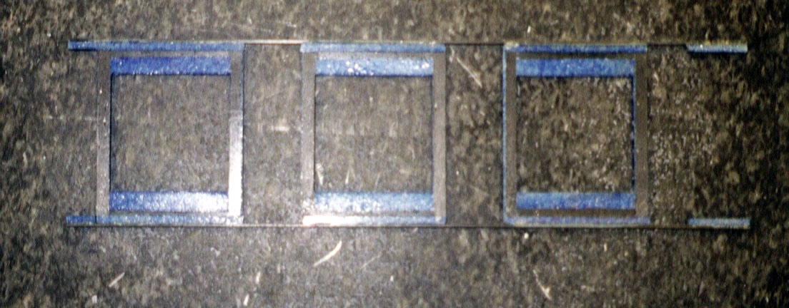
- (1) Half ladder frame.
Three sensors and a hybrid are glued on to this ladder frame.
The frame body is made of carbon fiber bars (black in photo) with Rohacel
(colored blue due to glue) foam. Since carbon is electrically conductive,
sensors are glued on Rohacel bars next to the long carbon fiber bars.
This part of Rohacel bar is reinforced by having a structure of stacking
Rohacel bars and carbon fiber bars.
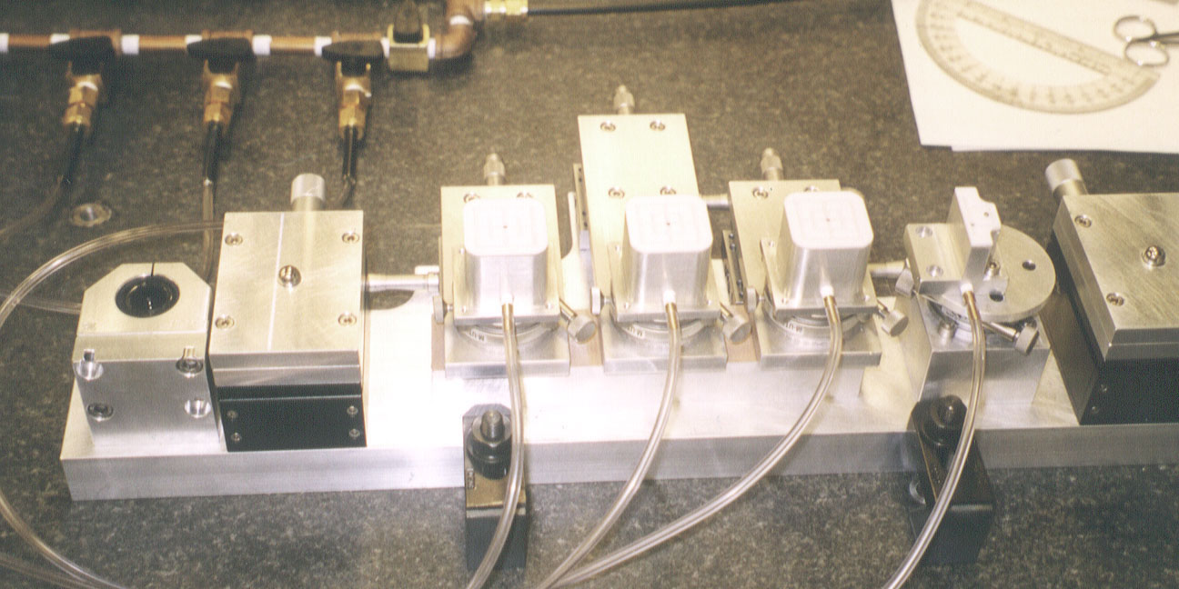
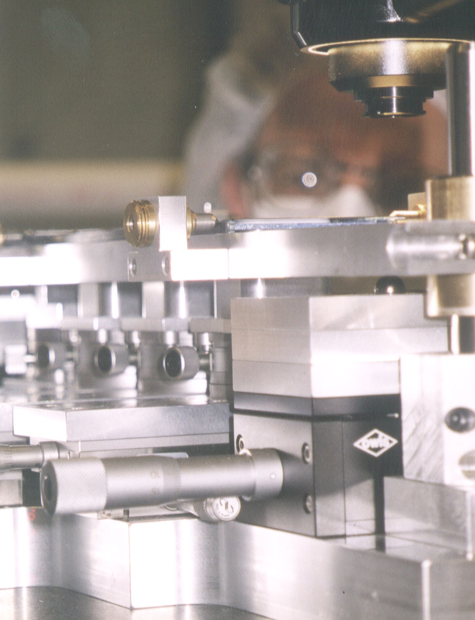
- (2) Sensor alignment stages.
Three stages for sensors and one smaller stage for hybrid with
teflon surface and vacuum chucking systems.
The stages can be individually positioned in X-Y (horizontal plane) and
rotated. The jig has two sets of linear bearings at the ends (one is out
of photo), using which a plate with the half-ladder frame placed can be
positioned vertically (see next photo).
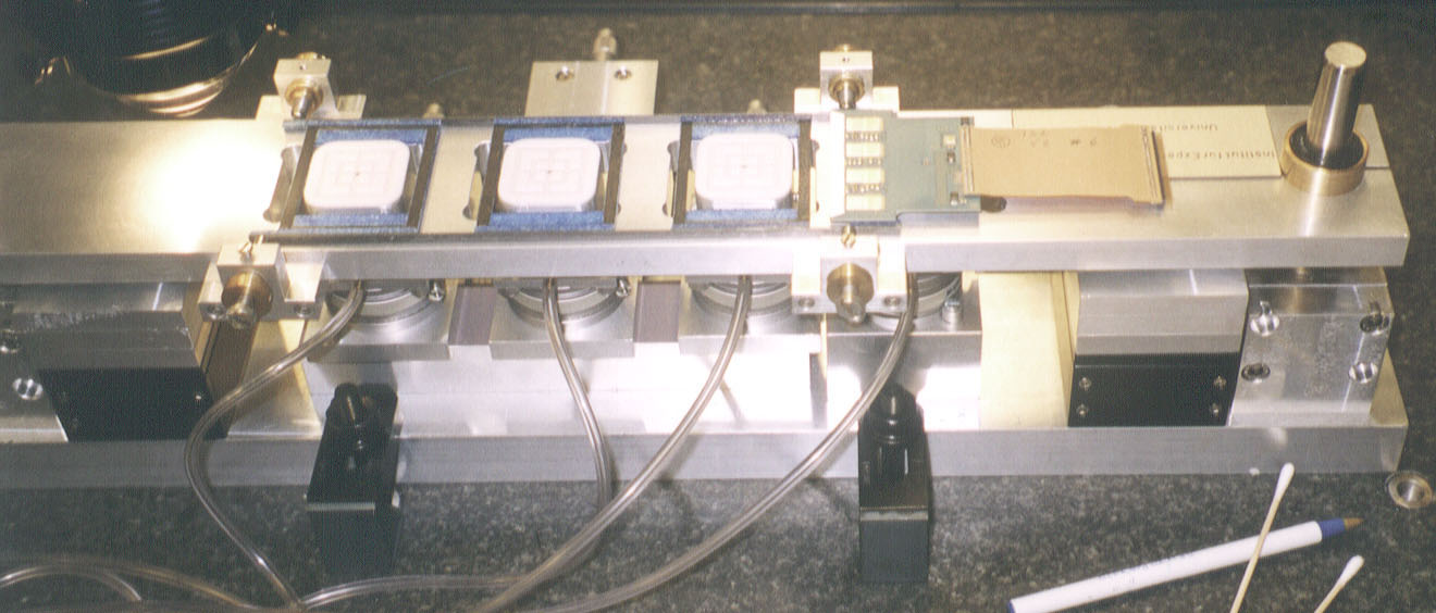
- (3) Hybrid is placed.
A plate is placed using linear bearings. On this plate a half-ladder
frame is positioned (temporarly) with spring-loaded pins at the four
sides. The teflon stage face is higher than the frame face so that
sensors and hybrid can be vacuum chucked without touching the frame.
The hybrid is positioned about a dowel pin, with the hybrid edge aligned
along the coordinate of the measurement system.
- (4) Measure the dowel pin position.
Measure the position of the dowel hole made in the hybrid. The hole
center is calculated from 8 measurements around the hole. The coordinate
system is thus defined, and the fiducials will be positioned (see below)
according to the design. The half-ladder frame is re-positioned at this
stage.
- (5) Place the 1st sensor.
The 1st sensor is placed. The r-phi strip side (n-side) is faced up.
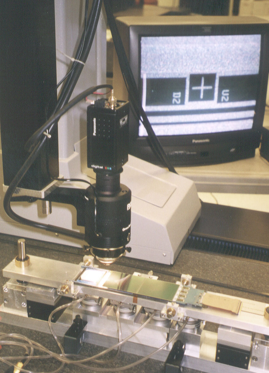
- (6) Place the 2nd sensor.
The 2nd sensor has been placed. Like for the 1st sensor, the two fiducials
along the median line are positioned. The TV monitor shows one of the
fiducial and cross-hair of the measurement system. Typically precision
of 2 microns is achievable. The 3rd sensor is similarly positioned.
- (7) Apply the glue.
Epoxy glue (Hexcel 5313 with DEH24 hardener) is applied on Rohacel foam
using a syringe.
- (8) Adjust the frame Z position.
The plate with the frame is lifted up by two balls underneath near
the linear bearings. The sensors and hybrid are to be faced to the frame.
At this stage, the sensor positions are re-adjusted to correct for
any shifts during the assembling process.
The whole process takes approximately two hours.
Wait for 24 hours till the glue is completely cured.
The vacuum is released and the position of each sensor is surveyed at
the four fiducials at the corners.
- (8) Bonding.
Wire-bond to the fanout and between the sensors. The half-ladder frame
is designed such that the head of wirebonder is not interfered. Need
a long (vertical) head, though, in order to bond the backside (stereo
side). It takes typically 1.5-2 hours per side.
Two such half-ladders are mated on a stage (no photo) and epoxied
together using L-shaped carbon fiber pieces.
- (9) Set on the spaceframe.
The ladders are placed on the spaceframe. The main parts are molded
carbon fiber rings with carbon fiber rods joining them together.
The photo is one side of the spaceframe. Identical another spaceframe
will be mated from right with rods joining them together.
Be plates glued on the spaceframe define the positions of the ladders.
Al cooling pipes run underneath the Be plates.
- (10) Another photo of the spaceframe.
Two ladders are placed as a test, each for the inner and outer
layers of the forward barrel.
Production Sensors Delivery
The original plan and current status of the delivery as of December 23, 1999
Delivery history in plot
Class B sensors pass relaxed specs defined in Jan 99
Class C sensors are for electrical checks delivered to U. of Tsukuba
| | Oct.98 | Nov.98 | Dec.98 | Jan.99 | Feb.99 | Mar.99 | Apr.99 | May.99 | Jun.99 | Jul.99 | Aug.99 | Sep.99 | Oct.99 | Nov.99 | Dec.99
|
|---|
| Original plan | 60 | 60 | 60 | 60 | 60 | 60 | 60 | 60 | 70 | | | | |
|
|---|
| Delivered | 0 | 20 | 4 | 27+18B | 34+15B | 40+32B
| 28+10B | 8+6B | 0 | 19 | 39 | 87+15B | 13+2B | 31+7B | 37+8B | - |
|
|---|
| +ClassC | 0 | 3C | 1C | 0 | 0 | 10C | 0 | 0
| 0 | 11C | 0 | 0 | 0 | 0 | 0 | -
|
|---|
| Accepted | 0 | 20 | 4 | 27+13B | 34+12B | 39+22B
| 28+10B | 8+5B | 0 | 19 | 39 | 87+15B | 13+2B | 31+7B | 37+8B |
|
|---|
| Use as C | 0 | 0 | 0 | 3B | 3B | 11B
| 0 | 1B | 0 | 0 | 0 | 0 | 0 | 0 | 0 | -
|
|---|
| Returned | 0 | 0 | (1) | 3 | 0 | 0 | 0
| 0 | 0 | 0 | 0 | 0 | 0 | 0 | 0 | -
|
|---|
| Skipped serial# | 0 | 0 | 0 | 0 | 0 | 0
| 0 | 0 | 2 | 0 | 0 | 1 | 0 | 0 | 0 | -
|
|---|
| Accept sum | 0 | 20 | 23 | 51+11B | 85+23B | 124+45B | 152+55B | 160+60B | 160+60B | 179+60B | 218+61B | 305+75B | 318+77B | 349+84B | 386+92B | -
|
|---|
 CDFnote on B class sensors
.GIF)